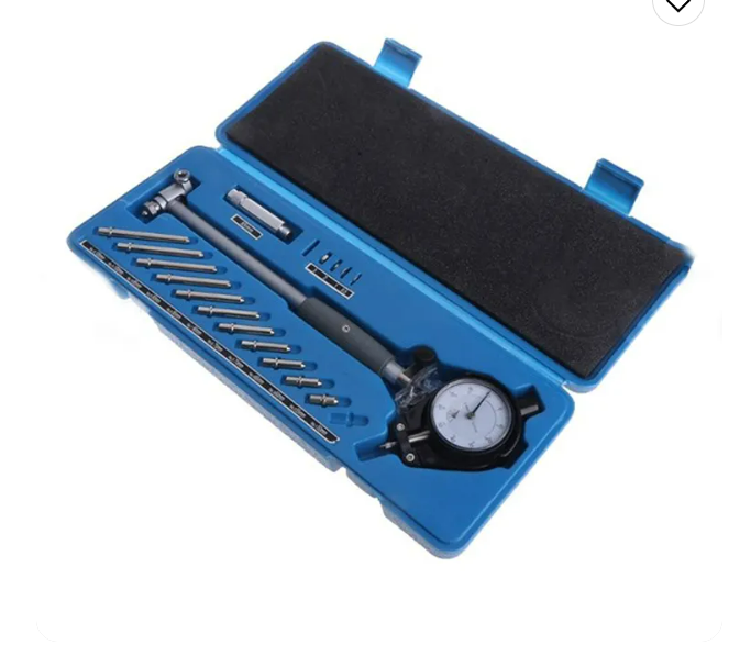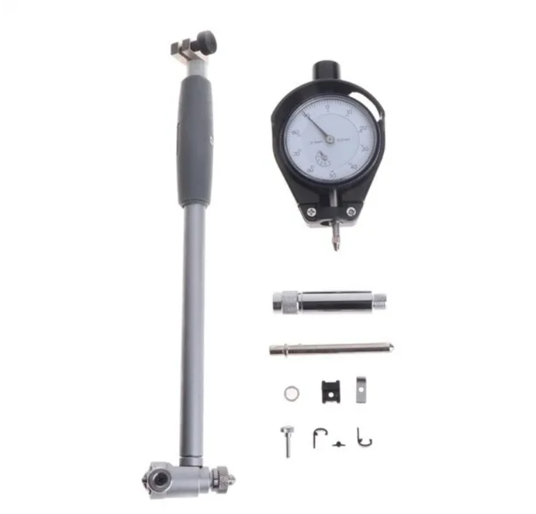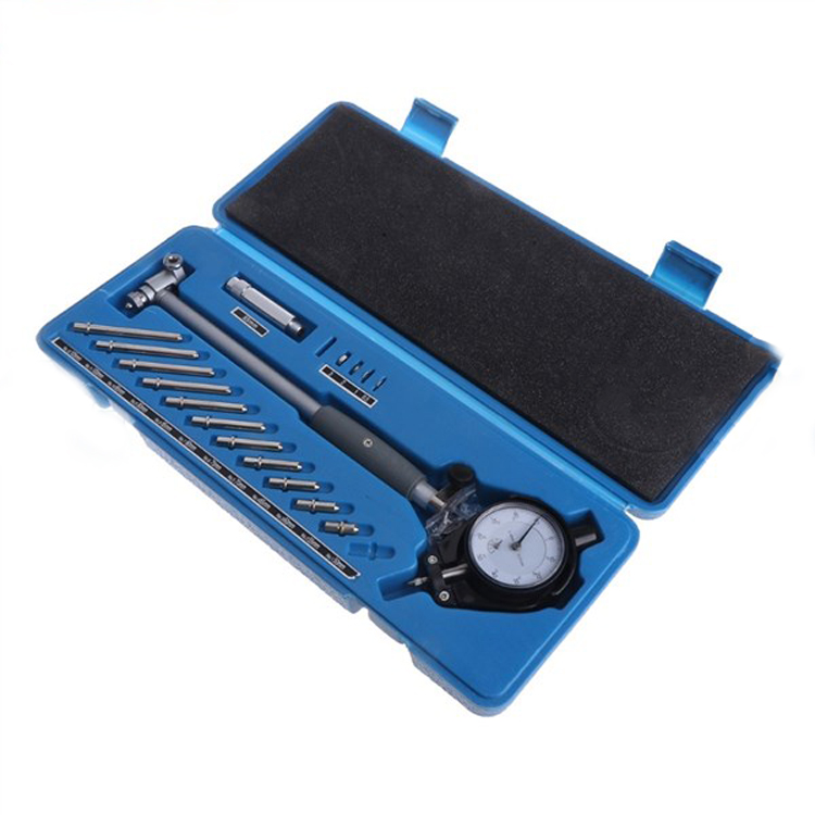
Indicateur à cadran de diamètre intérieur
Indicateur à cadran de diamètre intérieur
The surface roughness of the expansion spring-type inner diameter gauge does not exceed 0.1um. The measuring steel of the steel ball-type inner diameter gauge
The surface roughness of the ball and positioning steel ball shall not exceed 0.05um. Radius sample for probe spherical radius
Board comparison. The requirements are all less than 1/2 of the lower measurement limit size.
Calibration operation:
- Before calibration, the time for the calibrated inner diameter gauge and the standard instrument to be used is generally not less than 2 hours in the calibration room.
- First check the appearance of the inner diameter gauge to determine if there are any factors that affect the calibration measurement characteristics. Par exemple: the movement of the measuring mechanism of the inner diameter gauge should be smooth, flexible, and free of jamming and blockage. Each probe should be easy to replace and should be stable and reliable after tightening.
- Check the surface roughness of the measuring surface of the probe and the spherical radius of the probe. Use rough surface
Roughness comparison sample comparison. It is required that the surface roughness of the inner diameter gauge probe with positioning guard bridge, the measuring surface of the movable probe and the contact surface of the positioning guard bridge shall not exceed 0.2um. - The calibration of the indicator is carried out in accordance with the requirements of JJG34-2008 “Calibration Regulations for Indicators”.
- Calibrate the working stroke of the movable probe.
- Use the hand compression belt to position the movable probe of the inner diameter gauge of the bridge guard, and read the data on the indicator gauge.
- Use your hands to compress the expanding spring probe of the expanding spring-type inner diameter gauge twice, and read the reading on the indicator gauge.
- Use a micrometer to measure the steel ball inner diameter gauge and measure the working stroke of the steel ball.
When measuring, be sure to place the two measuring steel balls between the micrometer anvil and the micrometer screw, et
Make the axis of the two steel balls consistent with the axis of the micrometer screw. - Calibrate the force measurement of the movable probe and the contact pressure of the positioning guard bridge.
- The inner diameter gauge with positioning guard bridge is placed on the measurement where the inner diameter size is equal to the inner diameter gauge.
within the smooth ring gauge and the lower limit of measurement. When positioning the guard bridge at these two positions, mark the
remember. Then the contact surface of the positioning guard bridge is brought into contact with the end surface of a cylindrical auxiliary table placed on the force measuring device, and the pressure is applied downward. When the positioning guard bridge is compressed to the position of the upper and lower measurement limits, read the readings of the force measuring device respectively as the calibration results. - Place the spring-type probe or measuring steel ball between the measuring device and the pressure rod, and lower the pressure rod.
Compress the expansion spring probe or the measuring steel ball to the starting point of the working stroke, and the reading is on the measuring device, and then continue to compress the end point of the working stroke, and the indication value on the device is taken as the calibration result. - Correct calibration of the centering device. For the inner diameter gauge with a positioning guard bridge, compress the positioning guard bridge so that it does not work, put the inner diameter gauge into the special ring gauge, find the minimum size (turning point) in the axial plane of the ring gauge, and find the minimum size (turning point) in the radial direction of the ring gauge. Find the maximum dimension (turning point) in the plane, and determine the “reading” of the indicator when the two turning points are together. Then relax the positioning bridge guard and put in
At the same position of the ring gauge, find the minimum size reading in the axial plane of the ring gauge. The difference between the two readings is the calibration result. - The steel ball type inner diameter gauge is to first put the steel ball probe of the calibrated inner diameter gauge into the inner size composed of a measuring block with the same size as the special ring gauge.
and find the minimum size (turning point) in the plane perpendicular to the working surface of the blocks on both sides, and then “read
“Number”. When the indication values in the two directions are consistent, put it into the special ring gauge and place it on the axial surface of the ring gauge.
Find the minimum reading, and the difference between the two corrected readings is the calibration result. - Indication value variability calibration Calibration can be performed at any position during the working stroke. Put the inner diameter gauge into the special ring gauge, find the minimum reading on the axial surface of the ring gauge, and record the reading. Repeat the process 5 times at the same position. Among the 5 readings obtained, the difference between the maximum value and the minimum value is the calibration result.